Hi, Today we are going to make an rpm meter many times when working with a motor in your lab. You may have wondered what is the rpm of the motor or how the rpm meter works. So in today's post, we would be making our rpm meter from scratch. So let's get started …..
Table Of Content:- 1.HOW A RPM METER WORKS 2.BUILDING THE LOGIC 3.COMPONENTS WE NEED 4.CIRCUIT DIAGRAM 5.GIVING IT SHAPE 6.CODE 7.TESTING
HOW AN RPM METER WORKS:-
In an rpm meter, there is a sensor that senses the white portion on a black wheel or black portion on a white and counts the number of times the white portion comes in a minute. And display on the display.
BUILDING THE LOGIC:-
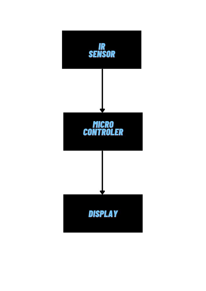
Now let's build the logic of an rpm meter as I have explained above how it works building logic would be very simple for us. Here we will build the logic in a block diagram.
Block Diagram
COMPONENTS NEEDED:-
Here I would like to recommend you to use Arduino nano because it has an inbuilt programmer and Arduino pro mini needs a external programmer.Use Vero board if you are like me and like to build circuits that can last long.
Table Of Components:- 1.Arduino Nano or Arduino pro mini 2.I2c Oled Display 3.IR Sensor 4.Beardboarb or Vero board 5.Battery ( OPTIONAL)
CIRCUIT DIAGRAM:-
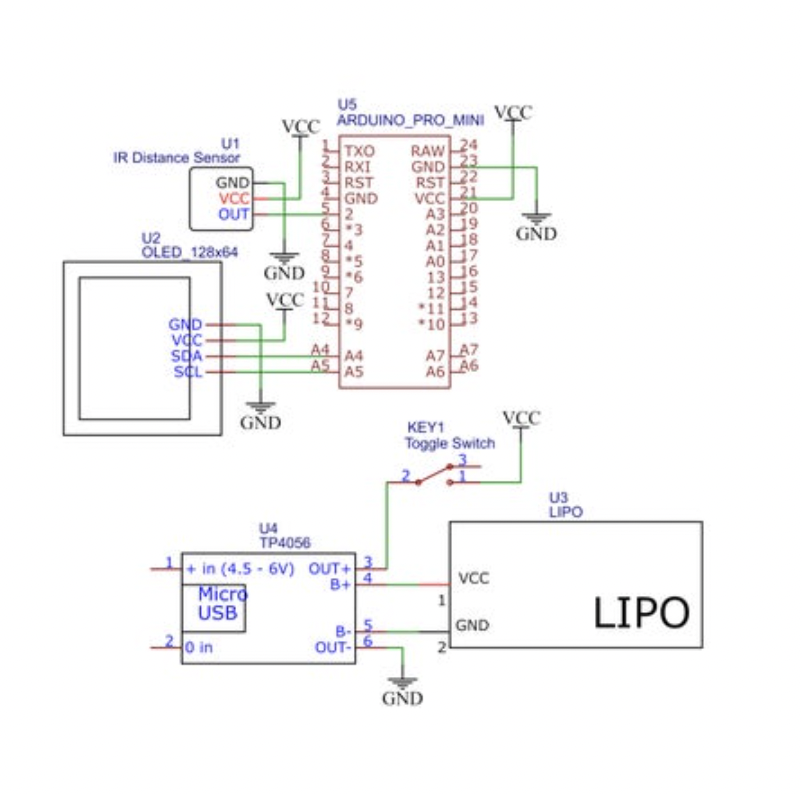
Here is a circuit diagram which i used . (here i have used an arduino pro mini but keep the pin numbers same if you use arduino nano or any other then only the code will work with other boards.
CIRCUIT DIAGRAM OR SCHEMATIC DIAGRAM
GIVING IT SHAPE:-
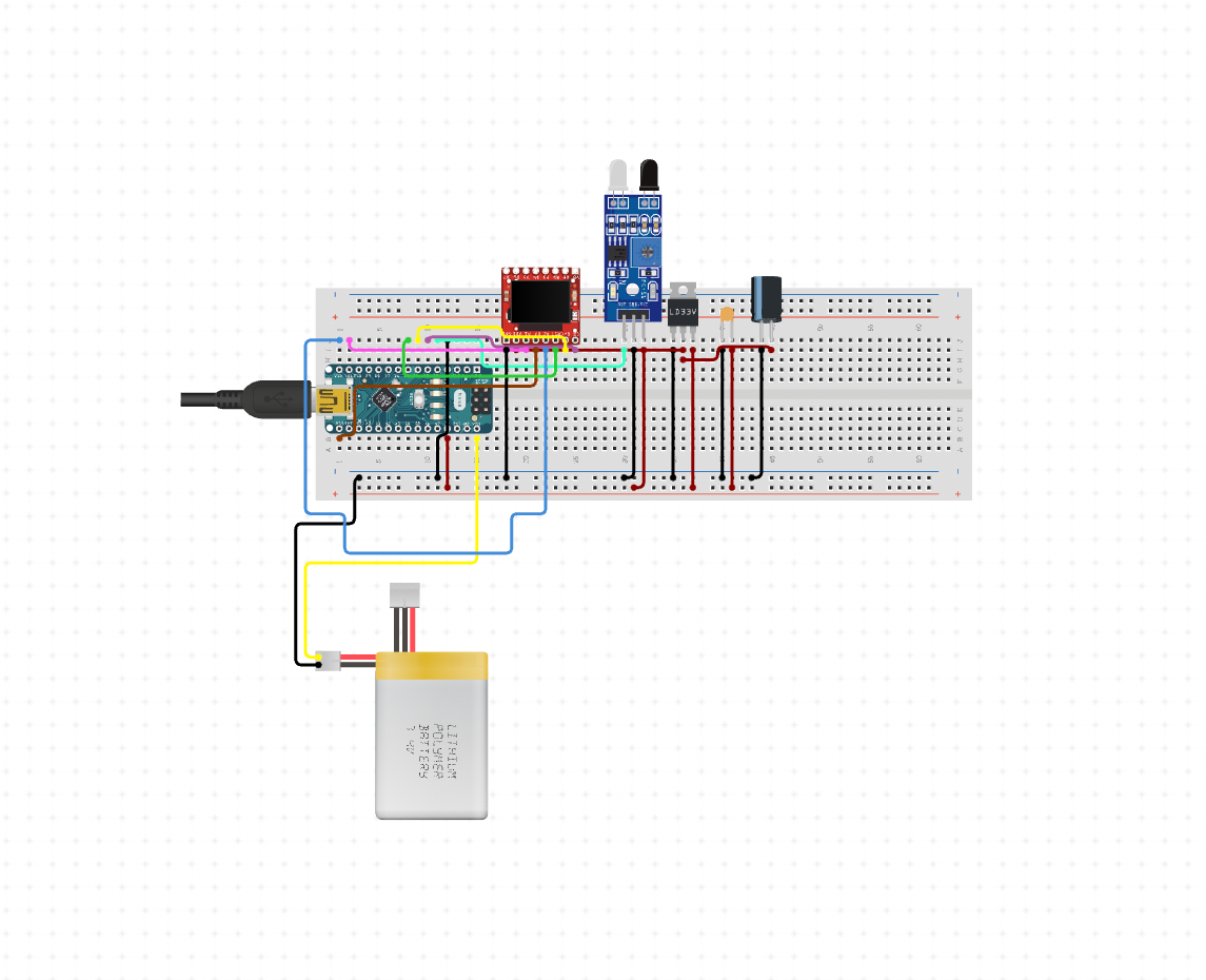
Now let’s build it. Step1:- Connect all the components as shown in the circuit diagram. Step2:- Create an enclosure according to your taste. Step3:- flash the code on the board THE PICTURE BELOW IS JUST FOR SHOW DON'T FOLLOW IT . FOLLOW THE CIRCUIT DIAGRAM ^.
A PICTURE TO IMAGINE HOW IT LOOKS.
C0DE:-
Now let’s flash the code on the board
/*  THIS IS MADE BY SHOURYA PANDEY
THE LIBRARY U8x8lib.h C++ Arduino wrapper for the u8x8 struct and c functions.
Universal 8bit Graphics Library
Copyright (c) 2021, olikraus
All rights reserved.*/
#include
#include
#include
#include
U8X8_SSD1306_128X64_NONAME_HW_I2C u8x8(/* reset=*/ U8X8_PIN_NONE);
unsigned long rpmtime;
float rpmfloat;
unsigned int rpm;
bool tooslow = 1;

void setup() {
  u8x8.begin();
  u8x8.setFont(u8x8_font_profont29_2x3_f);
  TCCR1A = 0;
  TCCR1B = 0;
  TCCR1B |= (1 << CS12); //Prescaler 256
  TIMSK1 |= (1 << TOIE1); //enable timer overflow
  pinMode(2, INPUT);
  attachInterrupt(0, RPM, FALLING);
}

ISR(TIMER1_OVF_vect) {
  tooslow = 1;
}

void loop() {
  delay(1000);
  if (tooslow == 1) {
    u8x8.clear();
    u8x8.drawString(1, 0, "SLOW!");
  }
  else {
    rpmfloat = 120 / (rpmtime/ 31250.00);
    rpm = round(rpmfloat);
    u8x8.clear();
    u8x8.setCursor(1,0);
    u8x8.print(rpm);
  }
}

void RPM () {
  rpmtime = TCNT1;
  TCNT1 = 0;
  tooslow = 0;
}
Testing:-
After testing the results were shocking. The results were quite accurate and impressive. The results were matching with the commercial one which I bought for around three thousand rupees. So I can say that if you want a tachometer or an rpm meter you can make your own at a very low cost.